PTC Engineering Note:
Switching PTC (Positive Temperature Coefficient) thermistors are solid state devices that exhibit several decades of resistance change over a narrow temperature range. This extremely large positive resistance change as the temperature increases generates many applications for these parts. Major applications include:
Typical Applications:
- Time Delay for Electronic Ballast
- Over Temperature Protection
- Over Current Protectors (Solid State Fusing)
- Self Regulating Heaters
- Degaussing
- Air Flow / Liquid Level Sensing
- Single Phase Motor Starting
Figure 1 illustrates a typical PTC curve. 
PTC Thermistors can be formulated to have switching temperatures
as low as zero (0) C to well over 200 C.
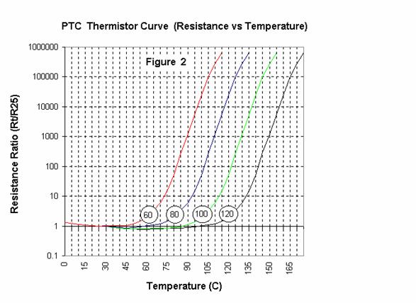
Figure 2 illustrates typical 60, 80, 100, and 120 C switching temperature
curves.

Figure 3 illustrates a static voltage / current curve. The static
voltage / current curve is very helpful in over current applications.

Terminology:
Base Resistance:
The resistance value of a thermistor at a specified temperature with negligible electrical power to avoid self heating.Usually base resistance will be defined at 25C.
Switch Temperature:
The temperature when the resistance of the PTC thermistor reaches two (2) times the base resistance, sometimes referred to as curie point or transition temperature.
Maximum Operating Voltage:
The maximum rated voltage the thermistor can continuously withstand (60 cycle AC or DC).
Dissipation Constant:
The amount of power through self-heating necessary to raise the thermistor body one (1) degree Celsius - units: Mw/C.
Time Constant:
The time, in seconds, required for a thermistor dissipating negligible power to change 63% of the total difference between its initial and final body temperature when subjected to a change in temperature.
APPLICATION NOTES:
Electronic Ballast Design:
PTC Thermistors are used in electronic ballast systems as a time delay element when the circuit is energized. The typical time delay that engineers design for is from 0.75 to 1.25 seconds. There are a great variety of circuit designs which lead to different PTC Thermistor requirements. The following is a general range of the PTC thermistor characteristics found in this application:
Physical Characteristics:
- Diameter: 0.150 - 0.250" (3.8 - 6.4 mm)
- Thickness (over leads and coating): 0.100 - 0.200" (2.5 - 5.1 mm)
- Lead Spacing: 0.200 +/- 0.020 (5.08 +/- 0.508 mm)
- Electrical Characteristics
- Base Resistance Ranges: 100 to 800 Ohms (varies with design)
- Switching Temperatures: 70 to 110 C
-
Maximum Voltages 250 to 750 volts
Over
Current Protectors:
Typical over current applications are:
- Telecommunication Line Protection
- Circuit Fault Protection
- Transistor Protection
- Motor and Transformer Protection
PTC Over Current Protectors are used in series to protect
from over current conditions. When a fault condition arises, the
PTC will heat up causing it to switch from its low resistance state
to a very high resistance. This very high resistance state will
reduce current flow to a safe level. Once this fault condition is
fixed, the PTC will cool to its normal (low) resistance state and
reset.
Several tables of Over Current Protectors are listed on this Web
Site at WECC
PRODUCTS.
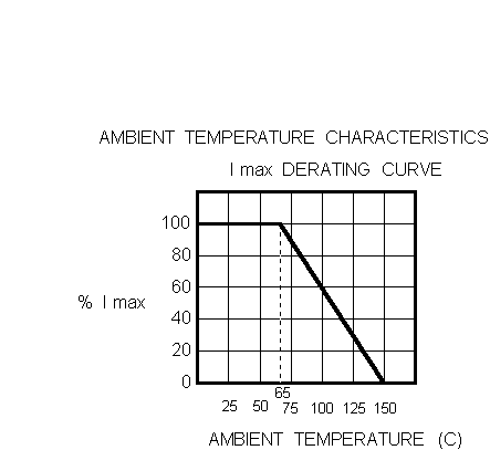
Figure 4 represents a typical PTC Thermistor curve used for over
current protection. The most common switching temperatures used
for these applications range from 110 to 135 °C.

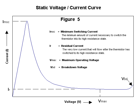
Figure 5 represents a typical static voltage / current curve. The linear part of this curve (below Imsc) allows a continuous amount of current to flow. When a fault condition arises and the current increases beyond Imsc (Minimum Switching Current), the PTC thermistor switches to a very high resistance state which limits the current to a very low level. Once the fault condition is eliminated, the PTC thermistor will cool and return to its normal low resistance state allowing the normal amount of continuous current to flow through the circuit
|


